On request, we will gladly deliver our motors and gearmotors with an integrated mechanical brake, which is available as single brake or double brake. The great number of available brake sizes and braking torques will certainly let you find the ideal brake for your specific requirements.
Find the right brake for you using our modular brake system
Double brake: The new component in our safe brake systems

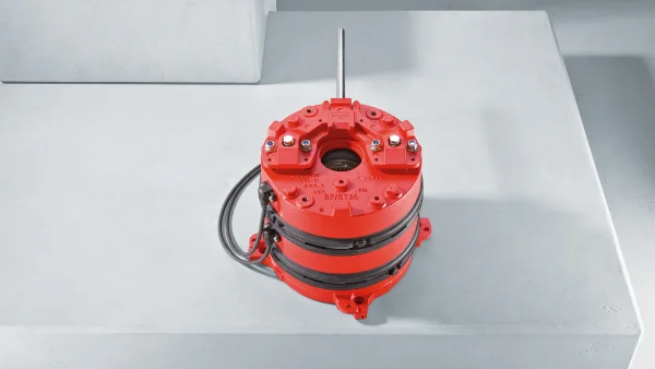
A popular solution for implementing safe brake systems in industrial environments or in event technology applications is the use of 2 parallel motors with individual brakes – a safe but not particularly compact or cost-effective solution.
With the state-of-the-art BF../BT.. double brakes, SEW‑EURODRIVE makes it possible for you to implement a safe brake system with 2 individual brakes on one single drive. Both of these double brake designs achieve the maximum performance level e (PL e) in industrial systems and event technology applications (in theaters, for instance).
The advantages of the double brake: Less installation space, less installation work and therefore lower costs. Supplementing a safe brake system, they provide completely new possibilities for man and machine in the area of functional safety.
Consult our sales team.
- Our experts know your industry and its requirements.
- Our global network ensures we are there wherever and whenever you need us.
- We have the expertise and the tools to provide optimum support and advice.
Your benefits
-
Short design
The weight and motor frame length are reduced thanks to the special design -
Large variety of options
Allows for custom combinations of motors and brakes -
Function and wear monitoring diagnostic unit (optional)
With a contactless, continuous supply of information regarding the function and wear of each individual brake -
Functional safety (optional)
With certification according to EN ISO 13849-1. For the area of event technology, the requirements of DIN 56950-1 are complied with.
BF../BT.. double brakes for DR..-series motors
Features
Overview of features
| BF.. double disk brake | BT.. double disk brake |
|---|---|
| Designed for applications in an industrial environment | Designed for applications in the event technology sector |
| Optionally designed as a safe double disk brake for use in "functional safety" as per EN ISO 13849-1 | Always designed as a safe double disk brake for use in "functional safety" as per EN ISO 13849-1 |
| Supplements a safe brake system up to maximum performance level e | Supplements a safe brake system up to maximum performance level e |
| Equipped and certified according to DIN 56950-1 for event technology | |
| Exceptionally quiet thanks to special damping features |
Brake options
As well as the HR manual brake release with automatic re-engaging function that can be used to release both individual brakes in the double disk brake simultaneously, a new HT manual brake release option is also available. In addition to the basic function of the HR option, it includes a special mechanical component on the manual release lever. This allows for the release of either of the individual brakes or both of the brakes together.
The double disk brakes are available from August 2015 in sizes BF11/BT11, BF20/BT20 and BF30/BT30 and with a rated braking torque from 2 x 20 Nm up to 2 x 300 Nm.
Special features:
- Manual brake release
- Contactless function and wear monitoring
- Special brake control
- Optional diagnostic unit for function and wear monitoring of the /DUE (diagnostic unit eddy current) brake
The sensor system provides continuous fully contactless function and wear monitoring for each individual brake. It displays the brake switching state, monitors the permitted wear and continuously measures the current working air gap.
Technical data
| BF.. | Spring-loaded double disk brake with size specification for industrial applications |
|---|---|
| BT. . | Spring-loaded double disk brake with size specification for theater applications |
Your choice of brake – possible brake combinations
| Motor type | Brake type | W insp 10 6 J |
Braking torque graduation Nm |
||||||||
|---|---|---|---|---|---|---|---|---|---|---|---|
| DR.112/132 |
BF11 BT11 |
2x285 2x190 |
2x20 | 2x28 | 2x40 | 2x55 | 2x80 | 2x110 | |||
| DR.160 | BF20 BT20 |
2x445 2x300 |
2x55 | 2x80 | 2x110 | 2x150 | 2x200 | ||||
| DR.180 | BF30 BT30 |
2x670 2x450 |
2x75 | 2x100 | 2x150 | 2x200 | 2x300 | ||||
The double disk brake can be used in industrial applications with or without "functional safety." The extremely quiet BT.. design with "functional safety," which meets all the specific requirements of event technology standards, is available for event technology applications (such as in theaters).
Functional safety
- BF.. safety-rated double disk brake (FS02) up to PL e in compliance with EN ISO 13849-1
- BT.. safety-rated brake (FS02) up to PL e in compliance with EN ISO 13849-1 and DIN 56950-1
- Static and dynamic brake diagnostics for SEW controllers (MOVI-PLC®/CCU) as a supplement to the brake
- BST safe brake module for safe brake control (SBC safety function) up to PL d in compliance with EN ISO 13849-1
Areas of application
- Industrial applications
- Event technology applications
Brakes for AC motors of the DR.. series
Features
Our DR.. motor series can be combined with the ideal BE.. brake to match your requirements for braking torque or braking work. Moreover, brakes mounted on motors larger than size 90 have an additional special feature. The brake itself is mounted on a friction plate, which only has to be attached to the end shield. That allows you to replace the unit with a larger or smaller brake without needing to open, remove or change the motor.
Our brakes can also be released mechanically when equipped with a manual brake release. Two options are available for manual brake release:
- For manual brake release with automatic reengaging function (..HR); a hand lever is included in the delivery.
- For the lock-type manual brake release (..HF), a set screw is included in the delivery.
You can choose from a range of brake controls for controlling disk brakes with a DC coil, based on the requirements and the operating conditions. All brake controls are fitted as standard with varistors to protect against overvoltage.
The brake controls are installed either directly in the terminal box on the motor or in the control cabinet. For motors of thermal class 180 (H) and explosion-proof motors (except the /3D category), the control system must be installed in the control cabinet. The different housings for the brake rectifiers have different colors (= color code) to make them easier to distinguish.
Brake control in the wiring space
The supply voltage for brakes with an AC connection is either supplied separately or taken from the supply system of the motor in the wiring space. The supply can come from the motor line voltage only when motors with a fixed speed are used. The supply voltage for the brake must be supplied separately with multi-speed motors and for operation with a frequency inverter.
Furthermore, bear in mind that the brake response is delayed by the residual voltage of the motor if the brake is powered by the motor line voltage. The brake application time specified in the technical data for the brake, which is t 2l for cut-off in the AC circuit, applies only when the supply is separate.
Technical data
Extract from the brake combination options
| Motor type | Brake type | W tot 10 6 J |
Braking torque graduation Nm |
|||||||
|---|---|---|---|---|---|---|---|---|---|---|
| … | … | … | … | |||||||
| DR..90 | BE1 | 120 | 5 | 7 | 10 | |||||
| BE2 | 165 | 7 | 10 | 14 | 20 | |||||
| BE5 | 260 | 14 | 20 | 28 | 40 | |||||
| DR..100 | BE2 | 165 | 10 | 14 | 20 | |||||
| |
BE5 | 260 | 14 | 20 | 28 | 40 | 55 | |||
| … | … | … | ||||||||
Overview of technical data
The type and number of brake springs used determine the level of the braking torque. Unless otherwise specified in the order, the brake is fitted with the maximum braking torque (M Bmax ) as standard when ordered as a single brake. The standard braking torque in the stand-alone motor and the gearmotor is dependent on nominal motor torque and can deviate from the maximum braking torque. Reduced braking torques (M Bred ) can be selected in the same brake size thanks to additional brake spring combinations.
| Brake type | M Bmax Nm |
Reduced braking torques M Bred Nm |
W insp 10 6 J |
t 1 10 -3 s | t 2 10 -3 s | P B W | ||||||
|---|---|---|---|---|---|---|---|---|---|---|---|---|
| BG | BGE | t 2 II | t 2 I | |||||||||
| BMG02 | 1.2 | 0.8 | 15 | 28 | 10 | 100 | 25 | 15 | ||||
| BR03 | 3.2 | 2.4 | 1.6 | 0.8 | 200 | 25 | 3 | 30 | 26 | 200 | ||
| BE05 | 5.0 | 3.5 | 2.5 | 1.8 | - | - | 120 | 34 | 15 | 10 | 42 | 32 |
| BE1 | 10 | 7.0 | 5.0 | - | - | - | 120 | 55 | 10 | 12 | 76 | 32 |
| BE2 | 20 | 14 | 10 | 7.0 | 5.0 | - | 180 | 73 | 17 | 10 | 68 | 43 |
| BE5 | 55 | 40 | 28 | 20 | 14 | - | 390 | - | 37 | 10 | 70 | 49 |
| BE11 | 110 | 80 | 55 | 40 | 20 | - | 640 | - | 41 | 15 | 82 | 76 |
| BE20 | 200 | 150 | 110 | 80 | 55 | 40 | 1000 | - | 57 | 20 | 88 | 100 |
| BE30 | 300 | 200 | 150 | 100 | 75 | - | 1,500 | - | 60 | 16 | 80 | 130 |
| BE32 | 600 | 500 | 400 | 300 | 200 | 150 | 1,500 | - | 60 | 16 | 80 | 130 |
| BE60 | 600 | 500 | 400 | 300 | 200 | 2500 | 90 | 25 | 120 | 195 | ||
| BE62 | 1200 | 1000 | 800 | 600 | 400 | 2500 | 90 | 25 | 120 | 195 | ||
| BE120 | 1000 | 800 | 600 | 400 | - | - | 390 | - | 120 | 40 | 130 | 250 |
| BE122 | 2000 | 1600 | 1200 | 800 | - | - | 300 | - | 120 | 40 | 130 | 250 |
|
||||||||||||
Brake control systems ...
The following tables list the technical data for brake control systems for installation in the motor terminal box and in the control cabinet. The different housings have different colors (= color code) to make them easier to distinguish.
... In the terminal box
| Type | Function | Voltage | Holding current I Hmax A |
Type | Publication number | Color code |
|---|---|---|---|---|---|---|
| BG | Half-wave rectifier | AC 230 – 575 V | 1.4 | BG 1.4 | 827 881 4 | Black |
| AC 150 – 500 V | 1.5 | BG 1.5 | 825 384 6 | Black | ||
| AC 24 – 500 V | 3.0 | BG 3 | 825 386 2 | Brown | ||
| BGE | One-way rectifier with electronic switching | AC 230 – 575 V | 1.4 | BGE 1.4 | 827 882 2 | Red |
| AC 150 – 500 V | 1.5 | BGE 1.5 | 825 385 4 | Red | ||
| AC 42 – 150 V | 3.0 | BGE 3 | 825 387 0 | Blue | ||
| BSR | Half-wave rectifier + current relay for switch-off in the DC circuit | AC 150 – 500 V | 1.0 | BGE 1.5 + SR 11 | 825 385 4 826 761 8 |
Red - |
| 1.0 | BGE 1.5 + SR 15 | 825 385 4 826 7621 8 |
Red - |
|||
| 1.0 | BGE 1.5 + SR19 |
825 385 4 826 246 2 |
Red - |
|||
| AC 42 – 150 V | 1.0 | BGE 3 + SR11 | 825 387 0 826 761 8 |
Blue - |
||
| 1.0 | BGE 3 + SR15 | 825 387 0 826 762 6 |
Blue - |
|||
| 1.0 | BGE 3 + SR19 | 825 387 0 826 246 2 |
Blue - |
|||
| BUR | Half-wave rectifier + voltage relay for switch-off in the DC circuit | AC 150 – 500 V | 1.0 | BGE 1.5 + UR 15 | 825 385 4 826 759 6 |
Red - |
| AC 42 – 150 V | 1.0 | BGE 3 + UR 11 |
825 387 0 826 758 8 |
Blue - |
||
| BS | Varistor protection circuit | DC 24 V | 5.0 | BS24 | 826 763 4 | Water blue |
| BSG | Electronic switching | DC 24 V | 5.0 | BSG | 825 459 1 | White |
| BMP | One-way rectifier with electronic switching, integrated voltage relay for switch-off in the DC circuit | AC 230 – 575 V | 2.8 | BMP 3.1 | 829 507 7 | - |
... in the control cabinet
| Type | Function | Voltage | Holding current I Hmax A |
Type | Publication number | Color code |
|---|---|---|---|---|---|---|
| BMS | One-way rectifier as BG | AC 230 – 575 V | 1.4 | BMS 1.4 | 829 830 0 | Black |
| AC 150 – 500 V | 1.5 | BMS 1.5 | 825 802 3 | Black | ||
| AC 42 – 150 V | 3.0 | BMS 3 | 825 803 1 | Brown | ||
| BME | One-way rectifier with electronic switching as BGE | AC 230 – 575 V | 1.4 | BME 1.4 | 829 831 9 | Red |
| AC 150 – 500 V | 1.5 | BME 1.5 | 825 722 1 | Red | ||
| AC 42 – 150 V | 3.0 | BME 3 | 825 723 X | Blue | ||
| BMH | One-way rectifier with electronic switching and heating function | AC 230 – 575 V | 1.4 | BMH 1.4 | 829 834 3 | Green |
| AC 150 – 500 V | 1.5 | BMH 1.5 | 825 818 X | Green | ||
| AC 42 – 150 V | 3.0 | BMH 3 | 825 819 8 | Yellow | ||
| BMP | One-way rectifier with electronic switching, integrated voltage relay for cut-off in the DC circuit | AC 230 – 575 V | 1.4 | BMP 1.4 | 829 832 7 | White |
| AC 150 – 500 V | 1.5 | BMP 1.5 | 825 685 3 | White | ||
| AC 42 – 150 V | 3.0 | BMP 3 | 826 566 6 | Light blue | ||
| AC 230 – 575 V | 2.8 | BMP 3.1 | 829 507 7 | - | ||
| BMK | One-way rectifier with electronic switching, 24 V DC control input and cut-off in the DC circuit | AC 230 – 575 V | 1.4 | BMK 1.4 | 829 883 5 | Water blue |
| AC 150 – 500 V | 1.5 | BMK 1.5 | 826 463 5 | Water blue | ||
| AC 42 – 150 V | 3.0 | BMK 3 | 826 567 4 | Bright red | ||
| BMV | Brake control unit with electronic switching, DC 24 V control input and fast cut-off | DC 24 V | 5.0 | BMV 5 | 1 300 006 3 | White |
| BST | Safety-related brake control with electronic switching and DC link supply | AC 460 | 0.6 | BST 0.6S | 08299714 | - |
| AC 400 | 0.7 | BST 0.7S | 13000772 | - | ||
| AC 230 | 1.2 | BST 1.2S | 13001337 | - |
Functional safety
SEW‑EURODRIVE drives can be fitted with optional safety-rated components such as brakes and/or encoders.
An integrated safety-rated brake is clearly labeled by the FS logo (e.g. FS02) on the motor nameplate. This allows for the implementation of safety functions and their performance level evaluation according to EN ISO 13849-1.
Safety functions with our brakes
- SBA (safe brake actuation)
- SBH (safe brake hold)
Our static and dynamic brake diagnostics for the MOVI-PLC ® controller is also available as a supplement to the safe brake system.
Areas of application
- Deceleration of motion, e.g. powertrains, rotary tables, etc.
- Fall protection, e.g. hoists
- Positioning drives